
My last few articles have had a theme of printhead performance related to latency and the effect of printhead design through recirculation and tickle pulsing. The last one made a bit of an assumption about how piezoelectric drop-on-demand printheads are driven via waveforms, so in this post we will look at that topic in a bit more detail and explain why things like the number of droplets sizes can influence printing speed.
How Piezo heads Sing…
Just writing those words I got Coldplay in my head, but pop-rock references aside the term “singing” is one some of us inkjet lab folks do use on occasion. There’s quite a good reason for that too, since the way a piezoelectric printhead works is usually acoustic, mediated by pressure waves cause by electrical signals.
So that brings me back to my dictionary definitions, another 2024 theme. I particularly liked this version for a wave: a progressive disturbance propagated from point to point in a medium or space without progress or advance by the points themselves, as in the transmission of sound or light. In this case our medium is the ink, of course and the result of the “disturbance” is a drop!
A waveform is a deliberate change in voltage applied to a piezoelectric actuator with a specific timing to make use of the way the resulting wave behaves in the printhead. The simplest form is a “pulse” comprising two edges, either going up or down in voltage, depending on the print head design.
These pulses can be given a theoretical square shape, but since the piezo is a capacitor being driven by current from an amplifier circuit the actual shape of the voltage change is more of rounded trapezoid shown below. As a result, analogue drive electronics tend to be used to choose the slew rate of the pulse.
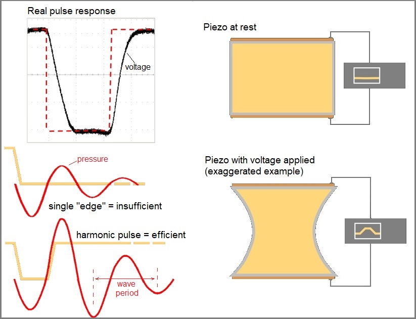
A square wave change in signal results in more of curve when applied to a piezo
We could get even more nerdy about the science here, but there are courses for that so instead we’ll just point out that the timing of the two edges of the pulse is one of the most important factors, alongside how tall it is (the “amplitude”) since that determine how hard you push the drops. This is because the second edge must coincide with the wave inside the head for the pulse to be “harmonic” and thus efficiently generate the pressure to push out a droplet. This is highlighted in the bottom left of the pictures above.
Turning grey with age?
The first printheads were just binary – they jetted one droplet size for every pixel in the raster – but it was not long before those clever piezo head developers thought how to make different size drops using the same acoustic principles. My PhD involved scanning tunnelling microscopy (STM) which also happens to work with piezoelectric and was invented by researchers at IBM Research, so my favourite greyscale example comes from an IBM patent shown below. One of the named inventors is Ross Mills, who I was very lucky to meet when I first worked in single pass printers for labels.
As described in the text of the patent, the key was to use the sub-pulse timing, τ, that was resonant or near-resonant, as derived by the size of the jetting chamber and the speed of sound of the ink. Just like the wave used to make a single pulse we just talked about shown as ω, in the patent image. These principles still hold today, although there have been lots of other clever inventions changing pulse heights and using different piezo geometries to reduce the required driving voltage.
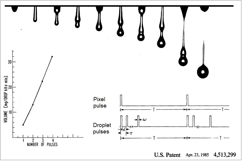
A seminal inkjet patent from IBM detailing how multi-pulsing can be used to make varied droplet sizes.
What’s the Frequency Kenneth?
Have you spotted how I am a sucker for music references? Never mind, I apologise to those who are not REM fans, but it is an important question nevertheless: What does using greyscale do to our maximum frequency?
Well, if you start putting a lot of jetting pulses one after another to make a choice of different droplet sizes then they are going to take time to finish, and the inverse of time is frequency, measured in Hertz (Hz). For any given addressability (in dpi) in the print direction this means print speed.
The calculation is easy, especially if you use inches/sec for print speed, although ft/min and m/min are the more popular choices:
Print speed = frequency / (drops/unit length)
Equally this can be rearranged, so that the maximum time available for any given pixel can be determined from the dpi and speed:
Pixel time = (drops/unit length) / print speed)
Let’s take a working example of 600dpi and 150m/min (~98.4inches/sec) = 59kHz (pixels/sec) which means a pixel occurs every (1000/59) = 17us. This means that any waveform required to print at that target has to finish this quickly and be ready to take the next instruction. The ability to create more than one droplet size means this frequency is limited to very fast printheads and small droplets.
We can look at that as a waveform schematic, assuming we want to have three droplet sizes to give 4 grey levels 0,1,2,3 (known as 2bits/pixel) then we might expect to have something like this:
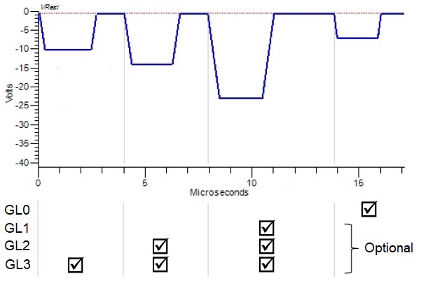
The biggest pulse (3rd one) is used for all grey levels. Each additional pulse is then added harmonically before to create a “right-had-justified” waveform. The final 4th pulse can be used as a tickle (see last post) or to help control droplet formation and is optional.
To fit all this into 17us pixel timing the pulse period is just 4us and that’s pretty much as short as it gets, so if you want to print grey levels at very high speeds (e.g., 200-300 m/min) you need to jet binary – which is actually quite common – or think of another way to do achieve it.
Sharing printed pixels between multiple heads is one way, thus reducing the frequency for each head. Indeed, this is often how it is done in thermal heads since the frequency is more limited by the bubble collapse. Another way with piezo heads is to have multiple waveform generators for pulses of different function or grey level, which is becoming a more frequent feature in newer Si-MEMS printheads.
Really piling up the pulses
If you want 8 grey levels (0-7 = 4 bits/pixel), then the limitation is more severe on maximum operating frequency. In the example below, an 8-pulse waveform is used to create up to 160pL droplets for a glass decorating application using a printhead from Seiko Instruments GmbH and a dropwatcher from Meteor Inkjet Limited (UK).
A non-specific example of the general waveform approach is shown, taken again from a patent because it is already in the public domain. The spacing of the pulses is related to the “acoustic length” of the PZT channel in which the ink flows. In this case that period is ~ 12us, so the total waveform time is ≤ 100us and the maximum frequency of the resulting waveform is 10kHz, which allows printing up to 42m/min at 360dpi. The is a perfectly acceptable speed in this application, since spinning bottle faster than this is going to get dangerous and messy!
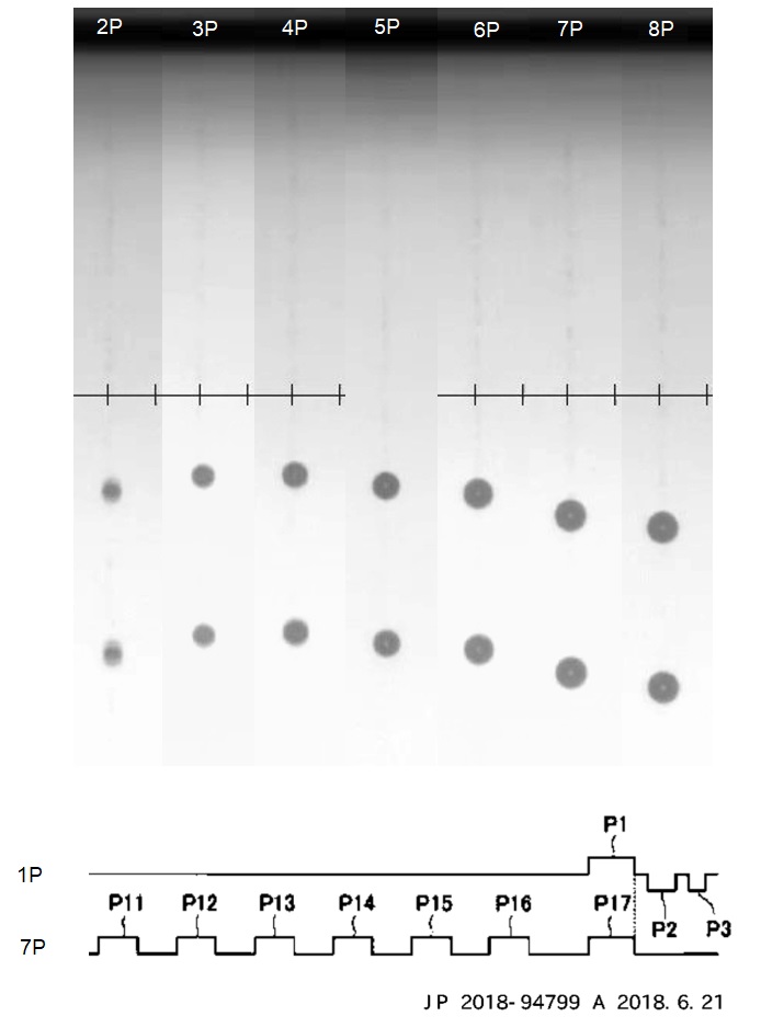
A practical example of a multidrop waveform from a Seiko RC head, which allows 8 greys (4bbp)
So, we have seen how increasing the number of drops tends to decrease the maximum print frequency. Therefore, we can effectively swap the increased “apparent resolution” of the process (dpi x √(greys)) for absolute “addressability” (dpi) and both together influence the ultimate print speed that is achievable. See the comparison in our previous article on labels for examples. The skill of a good OEM or integrator is optimising that combination to give the best possible print quality output.
In the next article in our lab-data-based printhead series we’ll give some examples of how heads behave at different frequencies.